Motorola 68008 computer with Arduino as ROM
After a fellow TkkrLab member donated some old chips (including some 68008 and Z80 CPUs) to the hackerspace I wanted to try to build a computer with the 68000 processor.
The 68008 processor is the 8-bit bus version of the 68000, which is the first 68k architecture processor. It is a 16-bit processor that was designed with forward compatibility in mind and to achieve that goal all of its internal registers (except for the status register) are 32-bits. The 68008 is interesting because it has a relatively low pin count and is therefore quite easy to use on a breadboard.
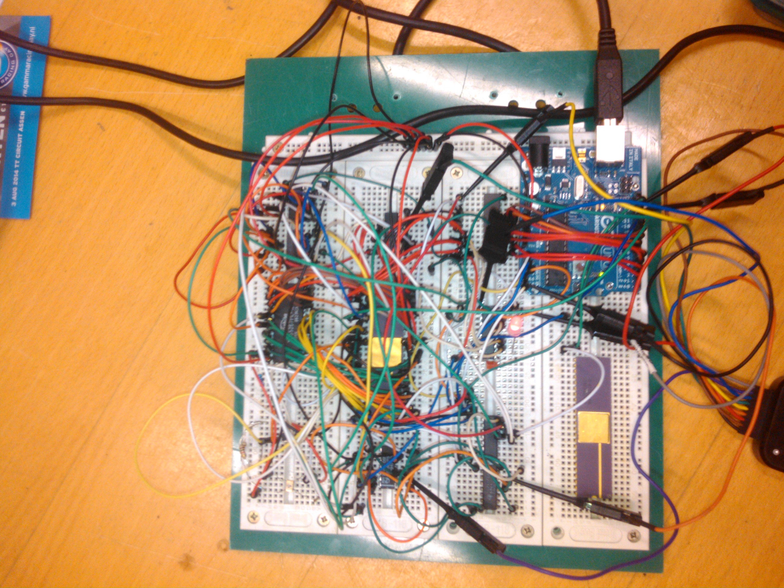
I looked up the datasheet for the processor and noticed that it allowed a device on the bus to add wait states as long as needed to complete a transfer, this sparked the idea to use an Arduino as “boot ROM”. I came up with a system where the arduino would dynamically generate 32 byte chunks of 68k machine code to load data into the RAM, disable the arduino bus interface and reset the processor afterwards, booting the new code from RAM.
The idea was simple: Make the glue logic map the first 64K of address space to the Arduino until it signalled boot complete, When that happened it would map the RAM to the first 64K and reset, executing the code that was uploaded.
The implementation yielded some interesting problems: First, the Arduino turned out to be too slow at releasing ~DTACK which caused the processor to assume every read was immediately completed until the arduino released the line. I fixed this by adding a D flip-flop with the D input tied high, the reset input connected to NOT ~AS and the clock connected to the Arduno. The inverting output of the flip-flop is connected to ~DTACK so that the Arduino can assert ~DTACK by setting the clock input high, and once the cycle is complete the processor will release ~AS and the flipflop will clear, causing ~DTACK to be released until the Arduino pulses the clock input again.
When this was fixed the setup would still not work: Although setting the reset vectors appeared to work (I have the Arduino log the adresses requested from it) I could not get it to run a simple “loop: jmp loop”… After a lot of trial and error I discovered i had not connected D7 from the Arduino, as soon as I fixed this it worked: The logs indicated the processor repeatedly fetching address 8 through 11, indicating it was actually looping.
I could, however, not write data anywhere as the Arduino was still way too slow at releasing the bus so I had to add a bus transceiver between the Arduino and the bus to prevent the Arduino and 68008 driving it at the same time.
While doing this I realized that I could never write to the RAM while the bootstrap mode was enabled: Temporarily disabling that mode as I had intended to do would have caused the ~DTACK line to be asserted immediately by the RAM on any cycle after that so the Arduino would not have been able to (reliably) disable it again. To solve this I decided to map the third 64K block of address space to the RAM without routing it through the bootstrap logic so that I can write to the RAM while the Arduino is still mapped on the first 64K.
Now that I finally had the design flaws ironed out I decided to write a simple program for the LED attached to the digital output:
M68000
DL 0
DL 8
MOVE.B #$FF, D1
MOVE.B D1, $010000
LOOP:
JMP LOOP
When I tried to run this code the processor would lock up after fetching the MOVE.B D1, $01000 instruction. Turns out I did not make the digital output register assert ~DTACK, causing the processor to wait for it forever. This was a simple fix: I added an inverter between the write enable input of the register and the ~DTACK output, causing the digital output register accesses to always complete immediately. I had now arrived at the (hopefully) correct glue logic combination to make this thing work.
Having done so much simple testing I wanted to finally see something happen on the breadboard and wrote this simple blink program:
M68000
DL 0
DL 8
MOVE.B #$FF, D1

LOOP:
MOVE.L #$FF, D0

LOOPW1:
SUBQ #1, D0
BNE LOOPW1

MOVE.B D1, $010000
NOT D1
BRA LOOP
Against all expectations, this worked right away: The led started blinking nicely, albeit very slowly: The Arduino fetches take 1 millisecond per byte.
I have not yet tried writing to the RAM or disabling the Arduino but the most tricky part of the build works: The slow 8-bit micro acting as ROM.
I have uploaded the Arduino code here and the schematics are available online here.